
Your contact pads are the weakest part of your encapsulation
A partner asked us how anyone takes the lead out of an encapsulated perovskite cell for outdoor testing. Here is what the published results actually do.
“Most partners use lab devices, cells mainly, where they have evaporated pads outside the encapsulant material. For outdoor installations, this could be a weak configuration. Do you also have partners who place samples outdoors? And if so, how do they take out the lead?”
He is right on both counts. It is a weak configuration, and yes, partners do put samples outdoors. They do it in three ways that are all published, and none of them involves an exposed pad.
We went back through every long-duration study we could find, including the ones that used our own material, and read what the method sections said about contacts and seals. One line from a 2025 master thesis out of the Bolink group in Valencia, which ran five encapsulation stacks outdoors for over a year using Eversolar® AB-341, sums up the pattern: the lifetime differences mapped “most clearly to edge/interface integrity rather than to the perovskite absorber itself”.
One number that puts a price on it
The most useful measurement in this field is one almost nobody reports: the lateral distance from the edge of the encapsulant to the edge of the active area. A team at Arizona State University and SUNY Buffalo measured what it is worth, and they happened to do it as a direct comparison of two of our grades.
They laser-ablated test structures down to an 8 by 8 mm active area, encapsulated them with two different cover glass sizes to give roughly 2.5 mm and 8.5 mm of seal width, and ran both through 200 thermal cycles.
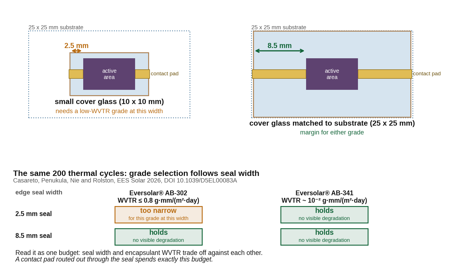
Eversolar® AB-302, which we specify at ≤0.8 g·mm/(m²·day), needs the wider seal. Eversolar® AB-341, two decades lower at roughly 10⁻² g·mm/(m²·day), held at both widths. Seal width and encapsulant barrier performance are one budget, not two independent choices.
Which is the real cost of an exposed contact pad. It spends that budget and returns nothing: it shortens the diffusion path across its own footprint, and it replaces the best interface in the package, adhesive onto clean glass, with one of the worst, adhesive onto evaporated metal. It also leaves the metal wet and biased at the same time, which is the condition under which silver reacts with halides and migrates.
Why the seal has to close onto glass
The Snaith group at Oxford has been designing around this for years, and they say so in the method section of paper after paper. From one of the Oxford theses:
“all material outside the perimeter of the rectangular glass cover slips was removed via scratching. This was to ensure that all glue deposited was in direct contact with the glass coverslip for proper encapsulation.”
And the same instruction, compressed to one line, in Nature Communications:
“Before encapsulation, perovskite material was removed at the epoxy edge for optimal adhesion.”
That is the adhesion hierarchy, applied. Eversolar® AB-341 bonds best to clean glass, and progressively less well to a dense inorganic film, to an evaporated metal, and to a bare perovskite surface. Scratching the perimeter clean before encapsulation is what guarantees the seal closes onto the strongest of those. An evaporated contact pad running out from under the cover glass undoes that step along its whole width.
The three ways it is actually done
All three share one principle: the metal film stays inside the package, and a separate conductor is bonded to it before anything is sealed.
1. Solder the wire, then bury it
Valencia ultrasonically soldered enamelled copper wire to the pads at 200 °C, then applied roughly 1 mm of Eversolar® AB-341 over the whole device and closed it with a cover glass. The Snaith group at Oxford did the same at roughly 2 mm. Valencia verified that the procedure does not measurably change the J-V characteristics. Both used it for outdoor MPP tracking over months.
2. Lay the ribbon between two layers of sealant
A ten-month outdoor study in Berlin compared two packages built from the same cells, the same tinned copper ribbon and the same electrical joint. In one the ribbon left the package underneath the structural adhesive; those cells failed at four days, six weeks and four months. In the other the ribbon sat between a lower and an upper layer of sealant, so that at the crossing the bond is sealant to sealant; those retained full initial efficiency for the whole ten months.
3. Follow the nine published steps
The supplementary information of a 2024 Nature Communications paper from Oxford, which used Eversolar® AB-341 to encapsulate its cells, defines a complete damp-heat procedure that reached 1,930 hours at 85 °C and 85% relative humidity. The device is bonded to the centre of a 70 by 70 mm glass plate with a transparent Eversolar® UV-curable epoxy, and the sealant is then built up around it in layers. On the conductor, the design point is that the ribbon sits between the first and the second layer of sealant.
Six rules
If you take nothing else from this note, take these.
- Route a conductor out, not the electrode.
The evaporated or sputtered metal terminates inside the sealed footprint. - Cap the metal electrode.
A dense inorganic layer over the electrode protects the device from unwanted chemical reaction at the contact: 250 nm MoO₃, 300 nm SiOx through an active-area mask, or thin ALD Al₂O₃. - Make the joint before you seal, and verify it.
Ultrasonic soldering, conductive ribbon tape, or copper tape with silver paste. Then a J-V scan, then encapsulation. Never the other way round. - Flat and thin beats round, with sealant above and below.
Lay a lower bead, place the ribbon into it, then lay the upper bead. The conductor must never exit from underneath the structural adhesive. - The seal lands on glass or on an inorganic film.
Never on parylene, never on bare perovskite. In the Valencia set, putting a parylene layer between the device and the Eversolar® AB-341 seal took T80 from 80 days down to three. - Spend the seal width budget on purpose.
Pick the width, then pick the grade whose barrier performance that width can afford, then check that nothing crossing the seal has eaten into it.
Where Eversolar® fits
Eversolar® AB-341 is the grade that appears in the published protocols above, and it is there for a specific reason. At roughly 10⁻² g·mm/(m²·day) and 70,000 mPa·s it has the barrier performance to protect a narrow seal and the body to be potted one to two millimetres deep around a solder joint without slumping. Eversolar® AB-341k pushes the barrier another decade at 240,000 mPa·s.
At the feedthrough itself, the 341 series replaces the butyl tape that the published recipes use. On the numbers each manufacturer publishes, and normalised for thickness, Eversolar® AB-341k is about sixty times lower in water vapour transmission than a commercial polyisobutylene PV edge sealant, at roughly twenty times the tensile strength. It is elastomeric after curing, which is the same property that makes butyl work at a joint that will be thermally cycled for years. And it cures in twenty-five seconds under a 405 nm LED at 0.3 W/cm² at room temperature, rather than needing fifteen minutes at 125 °C in a vacuum laminator.
The 405 nm option is the one we would specify for a finished device. Eversolar® AB-341k cures at either 365 or 405 nm, and 405 nm keeps the cure out of the UV-A band where perovskite absorbers, self-assembled monolayers and organic transport layers are most photosensitive. It costs a few seconds of exposure and removes a UV dose from a stack that has already been built.
One dispensed bead closes above and below the conductor in a single operation. That is the whole point.
The full technical note
The complete version covers five contact architectures with the test severity each one has actually reached, the working recipes with part numbers and cure schedules, the barrier comparison in full with its caveats, and grade selection by job. It is written for whoever in your group is about to put a sample on a roof.
Contact us for the full technical note, or for samples of any Eversolar® AB-series grade for a feedthrough trial or commercialization solution.
Gordon Chao · Everlight Europe B.V. · [email protected]
Sources
- M. Casareto, S. Penukula, W. Nie, N. Rolston. Hole-transport layer-dependent degradation mechanisms in perovskite solar modules. EES Solar, 2026. 10.1039/D5EL00083A
- B. M. Gallant et al., H. J. Snaith. A green solvent enables precursor phase engineering of stable formamidinium lead triiodide perovskite solar cells. Nature Communications, 2024. 10.1038/s41467-024-54113-4
- M. I. Gomar-Fernández et al. Large-area close-space sublimation enables the fabrication of efficient and stable perovskite solar cells. EES Solar, 2025. 10.1039/D5EL00145E
- M. V. Khenkin et al. Encapsulation and outdoor testing of perovskite solar cells: comparing an industrially relevant process with a simplified lab procedure. ACS Applied Materials & Interfaces, 2021. 10.1021/acsami.1c14720
- In situ growth and crystal monitoring for high-efficiency perovskite solar cells. Joule, 2026. 10.1016/j.joule.2026.102576
- G. Petrucci. Innovative encapsulation method for perovskite solar cells. Master thesis, Università di Pavia, 2024/2025. Experimental work carried out in the Bolink group, ICMol, Universitat de València.
- H.B. Fuller HelioSeal PVS 101 product datasheet, polyisobutylene edge sealant for photovoltaic modules. hbfullerproducts.com